
Leaf Mulcher Adapter
Ben Gillette · January 24th, 2020
One of my first projects was to create a fitting that could attach onto the end of a leaf mulcher, so that I could replace the refuse bag attached to the end with a shop vac hose. The hose would transport all of the leaves into our yard debris bin so when you’re mulching a pile of leaves, you don't have to stop and empty the bag into the bin. I had to focus on making sure the clip mechanism on top was measured and replicated as close as possible to the real thing so that it would attach when I was done.
The first step I took in modeling was to try and figure out how I was going to go about doing the general modeling of the shape. On this first rough draft I was just going for the rough shape of the fitting, and then I would add in the smaller details later. What I ended up doing was making a tube and then applying modifications to that tube as I went along. For the clip mechanism, I ended up setting a few offset planes, and then creating lofts that intersected tube. There were a couple big challenges that I had recognized at this point in the process. The first was that a lot of the measurements had to be estimated because they were either on lines that didn't exist on the actual fitting, or I was measuring a filited piece that I had to pretend was a square one. Another issue was the angling of a lot of pieces. Inside the fitting there were portions that were slanted at about 45 degrees to my estimate. These were really hard to get right, and on my first attempt, I made the angle on the back of the clip way to steep. Making the slants was only made harder by the fact that I had to lift every single object I created because the walls were bowed slightly inward. All of these challenges I had to address in the next version of my model.

The first part of creating the second version of my model was to extrude a tube with the same dimensions as the piece I was modeling. Then, I created a loft that would serve as the body for the clip mechanism. Using a loft allowed me to customize the angles of specific sides., and created the same “warped in” walls as on the piece I was modeling. Overall It served as the main shape, and all I had to do was add in small details and components.


The next step in making this version was to make the indents where part of the clip slotted in. I started out by offsetting the edge of the top trapezoid by two mm (the thickness of the wall) and then pushed the whole face in about 8 mm. I cut the offset profile into two pieces, and pushed the bottom section about halfway down the tube. This created two different sections for the clip: the bottom portion, which I had cut out, was done and nothing else had to be done to it. The top half would have the small membrane that held the slip in place and would also have a slanted wall running through it.

The final step in creating the model was to finish the part that helped the clip on. To do this I had to cut the top half remaining on the loft from the previous step at a 45 degree angle. The only challenge with this was that the walls were also slanted inwards, so I couldn’t just sketch and extrude. To create the slant, I made a loft so that the wall thickness stayed the same and just made the top profile of the loft really small. The next part was to make the whole for the actual clipping mechanism to slide into. For this, I offset the edges on the slant about 2 mm, and swept that straight out. From there I just cut down to little gaps that served as the membrane that held the clip in place, and the model was finished and ready to print.


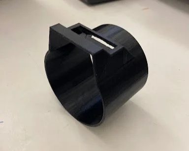
For printing, I placed the tube clip side down so that minimal support material had to be used, just enough to support the small membrane in the clip and that was it. I used a FlashForge Dreamer to print with a layer height of 0.18mm, a wall thickness of 2, and an infill of 15%. I chose to use 15% infill because the walls are thin enough already, and having a short print time and less filament used was okay. I used normal print quality to print, because I wanted a somewhat fast print time but the clip portion had to be in some detail as well. This type of process that I went through is probably done a lot in real world applications. Whether professionals need to make a model of a current product so that it can be manufactured in a different way, or if a custom part is needed for smaller projects currently existing components can be recreated in a modeling software, and then printed for use later.