
Puzzle Box
Ben Gillette · November 12th, 2020

Project Plan
My task for this project was to create a 3D object from 2D components laser cut from 1/8 inch plywood. I chose to make a puzzle box using a couple of mechanical components and small puzzles that locked the box. The first thing the person would have to do to open the box is to adjust the sliders on the bottom to match the symbols on the corresponding side. There are bars inside the box that prevent it from being opened until an open circle, triangle, hexagon, and closed triangle are put in on the bottom of the box. Then a small chamber is opened which gives a couple of small components that can be used to make a small crank to insert into the top of the box, which when twisted allows the lid to come off revealing whatever is put inside
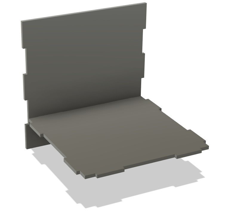
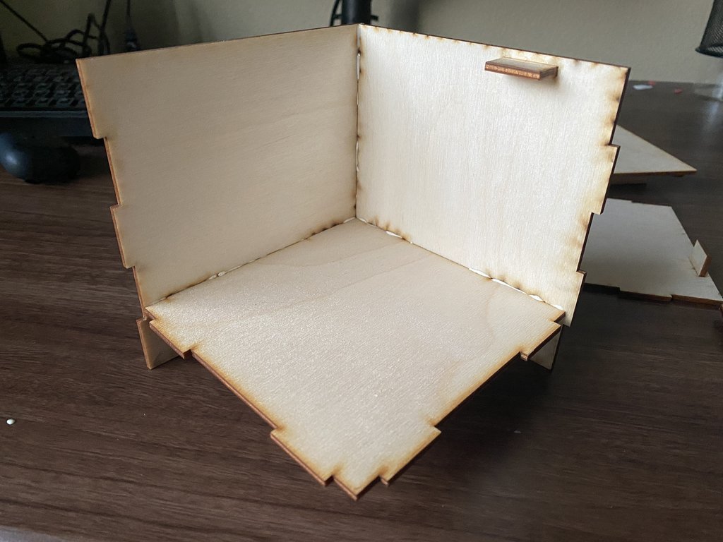
Constructing the Casing

The first step of building the puzzle box was to create the outside frame so I had a base to work off of and a frame to size all the components off of. I chose to make the box 5x5x5 inches so that it wasn't so big that it was unstable with the 1/8 plywood. But big enough that one could put something inside of it. Another thing I did with the casing that carried over to the entire project was leaving every piece as a separate body so I could later translate all the pieces flat on the work plane to export as a 2D .dxf file for laser cutting.
Crank Mechanism

The next step in this project was to start working on the mechanism to open the lid. I knew that I would be using gears to open the lid in some way so the first step I took was to build a crank that could be put in the top to turn them. I used a D shaped shaft with the same radius as the hole in the top of the box to turn the gears, then I added a crank body with a hole on the opposite end for a handle the slide into so the gears could be turned easier and with more force. The handle has a slightly larger circle on it so that it can be inserted into the crank and then move around freely similar to as if it were attached to a bearing.
Mechanical Components

The next step for the lid was to make the mechanism that locks the box. For this, I imported some corresponding spur gears and gear racks from the McMaster-Carr catalog and then deleted portions of the design until I was left with just the gear and racks. I did this because fusion has no other in-program function for creating gears and in addition, if I wanted to make this project out of metal I could have real components to order if needed. I created the gear and racks such that I could glue multiple layers of plywood together to make a sturdier component. The gear and racks are set up here so that when the gear is turned one way or another the racks are either retracted or extended which allows the lid to be locked on with the placement of some catches on the casing.
Finalizing the Lid

Inside the final lid piece

With my gears and racks in order, it was time to make the housing to hold everything together. If you look at the first picture you can see I used a series of pieces to make a channel that holds the racks in a straight line. I also made sure there was enough room for the racks to fully retract inside of the box so that they would be able to clear the catches in the casing later. In the second image, you can see the final assembled lid, where I simply added a bottom to hold the whole assembly in place and some holes in the side to allow the racks to slide in and out.
Installing the Lid Catches

Just a quick little addition here to the casing, I added two little wood pieces that are positioned so that when the lid is on and the gear racks are extended the wood pieces will 'catch' the racks and prevent the lid from lifting. To secure these to the casing I cut a small little notch in the walls that the catches would later be glued into.
Starting on the Bottom

My idea for the bottom of the box and the first puzzle a person would have to solve to open it was to have sliders one would have to match with the symbols on the sides of the box in order for the bottom to release. I went through a couple of drafts for this design but I eventually decided on the layout you see above. here there are actually two tracks for the sliders, the inside one being for stability and the outside being the home of the locking mechanism. In the laser-cut, there would then be two symbols for each slider, one on the left, and one on the right. The left symbol would be filled in and the right would be open. Once the sliders were moved the bottom panel would clear the latches, as detailed in the next section.
Constructing the Mechanism

As I touched on above, there are two tracks the slider is attached to, one on the inside which is just secured freely to the bottom for support as seen above, and the other on the outside to secure the bottom in place. You can see here that I have the sliders in the unlocked position, and you can also see the latches coming from the sliders which when moved from the correct position will catch on the rails (which will be glued to the main casing) preventing the lid from coming off.
False Bottom

The final component of my design that was missing was a false bottom so that the main compartment and auxiliary compartment would be separated. This allows you to keep what you want securely locked in the top (shown above) and the components to build the crank stored separately in the bottom.
Final Touches
The final step of design was to cut interlocking notches into the big panels of the casing so that they would fit together precisely, and make the box much stronger as the glue wasn't the only thing holding the case together. While this seems simple, it is a crucial step and makes the design last much longer, and even allowed me to assemble the box before gluing to make sure everything was working. I made the notches 1 inch long so that they wouldn't be so small it was hard to fit together, but there would be enough to help the structural integrity. Shown in the image above are one wall and the false bottom, but the same cuts were made to the other panels using a simple cut and extrude.
Getting a Ready-to-Cut File

The next step in the project was to flatten all the components I made onto the 2D work plane so I could export the file as a .dxf to the laser cutter. This is where the process I mentioned earlier of making sure every body in the assembled model was a 1/8 inch thick, completely separate piece. This step saved me an unimaginable amount of time which would've been spent re-separating the bodies if I hadn't taken this step. Because I had these separated pieces in my assembled model, all it took was copying the entire fusion file and then translating all the pieces flat so I had two files, an assembled model and a print file. The image you see above has the components organized into two sheets of 12x24 in (the size of the plywood sheets being used). You may also note the sketches shown in blue that are the shapes to be engraved (not cut) into the wood.
Adjustments to the Lid Mechanism

One small problem I ran into was that the racks weren't secured to the housing fully, and were able to move up and down as they were shorter than the compartment, unlike the gear. To fix this problem I took a couple of extra nubs from the gear and used them to create a limit so when the racks were fully retracted they wouldn't shift. You can see the addition as the little circles in the above image.
Further Adjustments to the Lid

Lid mechanism adjustments with the racks in place

Lid mechanism ready for gluing to the lid casing

Here you can see the final assembled lid. One thing you might notice is the small circles in the corners which weren't included in the design. I put these in place because I realized in testing that although you couldn't lift the box straight up when the racks were in place, you could shift it to the side and then up. To solve the issue I placed a couple of pieces left over from other components to sit just inside the casing edges when the lid was in place, preventing the lid from moving until it was unlocked.
Notes on Assembly

Bottom externals

Inside the bottom plate
Inside corner of the box during final gluing

Same corner of the box during assembly viewed from the outside
Main chamber of the box

Bottom compartment containing disassembled crank
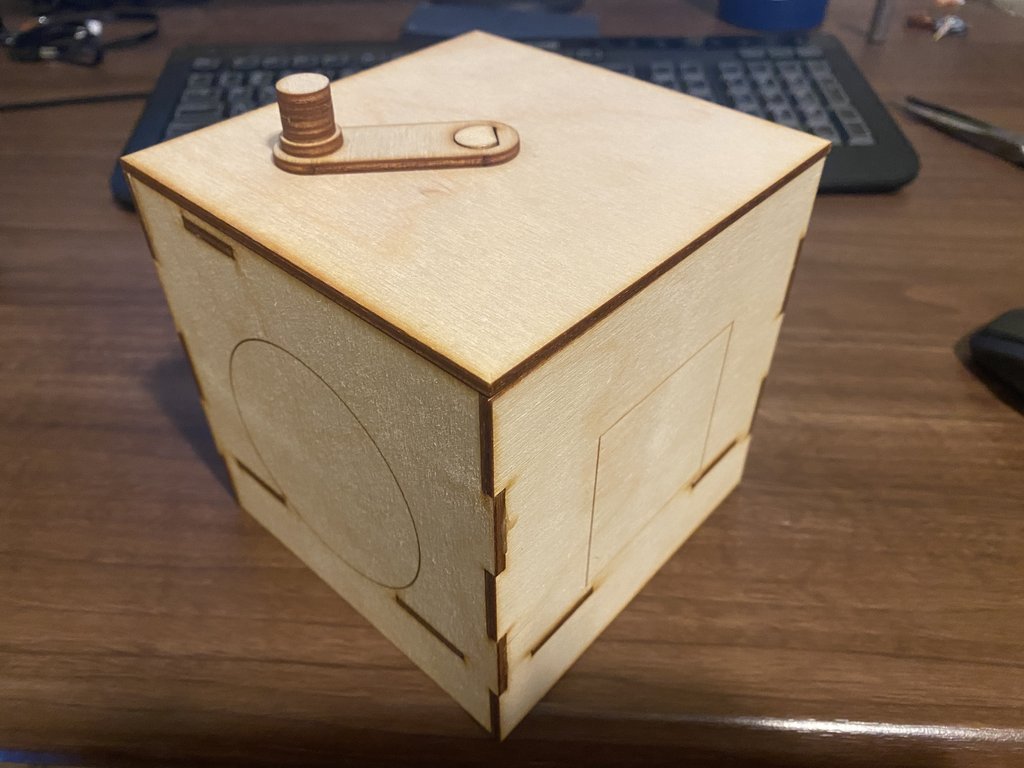
I ran into a couple of issues during the final assembly that you can see I solved with a couple of extra components above. However, other than those small issues I was thrilled with how the whole thing came out, all the pieces fit together nicely with the wood glue making for a very sturdy finished product. I did file out the rough edges for moving components in the bottom and lid mechanisms to make sure all the moving components could shift easily, and with those touch-ups, the final product is something I'm very proud of. I gave it to a couple of family members to open and they all managed to open it in just over a minute or so, which makes for a fun little thing to show off.
Having finally finished this project I can say that it was a really amazing and fun experience and I learned a lot from it. Working on a 3D object like this while also having to keep in mind that all the components had to be made from plywood made the puzzle box design difficult and slightly time intensive, but I had a ton of fun with the challenge. It gave me the opportunity to really think through every action I was making to think about how it would play out in the final product, and figuring out a way to make all the moving parts work with something like a puzzle box forced me to refine my workflow and plan every action. In the end, I think I learned a lot about design planning and how to think out every step of a project as you create it from this project, and I am proud to have created this.
Credit to McMaster-Carr for their models of the gears and gear racks I used to get the shape of mine in the final design.