
Useless Box Project
Ben Gillette · May 15th, 2022
My second project in Mechatronics was to create a useless box or a box that turns itself off. To add dimension to this existing idea, we also had to come up with some other functions to give the box “personality". For my project, I plan to create the standard useless box design with a servo arm that toggles the switch off. The arm will have a few different ways to turn off the switch, a standard poke, and a more annoyed poke. Every few cycles I will then have the box play a short clip of MC Hammer’s “U Can’t Touch This” before turning off the switch.
Design Process

To start my project I worked out the circuitry and coding side. My project consists of two parts: the servo motors that drive the lid and switch arm, along with the buzzer that played the tune. Shown above is my initial circuit for the inside of the box. One servo is responsible for toggling the switch, and the other is for opening the lid. Here is the code I made for testing the box in early stages:
// Ben Gillette Useless Box Project May 2022
#include <Servo.h>
// Declare the Servo pin
const int toggleServoPin = 3;
const int lidServoPin = 4;
const int togglePin = 12;
boolean toggle;
Servo toggleServo;
Servo lidServo;

void setup() {
   pinMode(togglePin, INPUT);
   toggleServo.attach(toggleServoPin);
   lidServo.attach(lidServoPin);
   Serial.begin(9600);
}
void loop(){
   if(digitalRead(togglePin) == HIGH){
    toggle = true;
    Serial.println("lid opens...");
    lidServo.write(0);
    delay(500);
    Serial.println("Switch flipped...");
    toggleServo.write(0);
    delay(500);
    toggleServo.write(180);
    delay(500);
    Serial.println("lid closes...");
    lidServo.write(180);
    delay(500);
   }
   else {
    toggle = false;
    Serial.println("off");
   }
   delay(100);
}
This early program toggles both switches 180 degrees, as I wouldn't know the exact angles until I calibrated the final product. Once I had the box assembled though, this code could be modified to flip the switch back to the off position. The next part was the music component. I created a separate test program and started by doing a simple tune of happy birthday on a piezo buzzer with the tone() function:
//Ben Gillette Happy Birthday Song May 2022
int beat = 200;
int beat2 = 400;
int beat3 = 600;
int beat4 = 800;
int half = 1600;

int G4 = 392;
int X4 = 440;
long B4 = 493.88;
long C5 = 523.25;
long D5 = 587.33;
long E5 = 659.25;
long F5 = 698.46;
long G5 = 783.99;

void setup() {
pinMode(7, OUTPUT);
Serial.begin(9600);
}

void loop() {
  Serial.println("start");
  tone(7, G4);
  delay(beat3);
  noTone(7);
  delay(40);
  tone(7,G4);
  delay(beat);
  tone(7, X4);
  delay(beat4);
  tone(7, G4);
  delay(beat4);
  tone(7, C5);
  delay(beat4);
  tone(7, B4);
  delay(half);
  tone(7, G4);
  delay(beat3);
  noTone(7);
  delay(40);
  tone(7,G4);
  delay(beat);
  tone(7, X4);
  delay(beat4);
  tone(7, G4);
  delay(beat4);
  tone(7, D5);
  delay(beat4);

  tone(7, C5);
  delay(half);
  tone(7, G4);
  delay(beat3);
  noTone(7);
  delay(40);
  tone(7,G4);
  delay(beat);

  tone(7, G5);
  delay(beat4);
  tone(7, E5);
  delay(beat4);
  tone(7, C5);
  delay(beat4);
  tone(7, B4);
  delay(beat4);
  tone(7, X4);
  delay(beat4);
  tone(7, F5);
  delay(beat3);
  noTone(7);
  delay(40);
  tone(7,F5);
  delay(beat);

  tone(7, E5);
  delay(beat4);
  tone(7, C5);
  delay(beat4);
  tone(7, D5);
  delay(beat4);
  tone(7, C5);
  delay(half);

}
The whole program is rather long, but I created it by programing in a score sheet to the code. By assigning the frequencies of different notes to variables, and setting each eighth, quarter and half note to a delay, the process of translating music is fairly simple. Happy birthday worked well, next I will try with the actual music on the buzzer, or possibly experiment with the Arduino wave shield for more sound options. The circuitry I have is fairly straight forward, everything is connected to ground, along with control pins to each servo and the piezo buzzer. The switch has one end that it connected to 5V, and the other that is connected to ground through a 10K resistor, and a digital input pin to read the switch status.
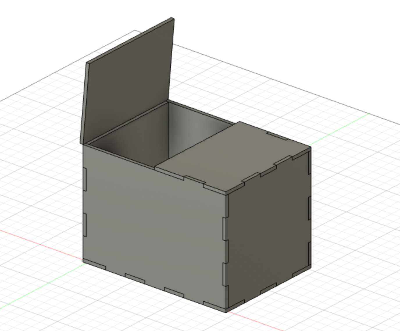
Box shell design from Fusion 360
The next step was to start working on the design files for the laser cut box. I started by building the shell in fusion, incorporating notches so the box would be more structurally sound. The process for making these was fairly simple, the entire design is going to be exported as a 2D cut file, but I assembled all the parts so I could visualize the final product. I had to make sure to size every component to 1/8 inch thickness, as that’s the plywood we had.
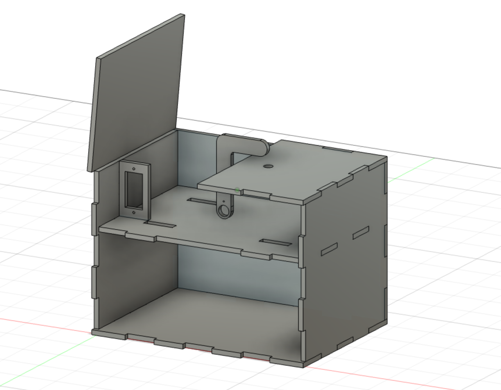
Second iteration of box design
The next part of the 3D design here was to create the internals of the box. I needed a couple components: servo mounts for the lid and toggle servos, a hole for the switch, a compartment for the electronics and control, and a way for wires to bo between those compartments. I created a style of mount for the servos that looks a bit like a light switch cover, but aligns such that the servo can mount with the built in screws. I also made the toggle arm, keeping in mind how big it would need to be and still fit in the housing. To solve my cable management issues, I divided the main compartment in two, the bottom to be used for Arduino and wiring housing. I cut the four slots in between as seen above so I would have plenty of area to run cables to the motors as needed.
The final step was to lay everything out in a separate file so it could be exported and cut. This image below shows all the individual panels I had as components of the box.

Components from cut file in Fusion 360 before heading to the laser cutter
Finally, it came to assembly, the final code and calibration, and the final product. Here below is my final wiring diagram, very similar to the initial prototypes, just with all the components not integrated into one circuit.

Complete circuit diagram
Completing the final program was simply a matter of coding in a score sheet for the song I used, calibrating the servo positions, and finally adding some “personality” to the box. I used a variable to track the number of times the switch had been flipped, and then had the box switch between different ways of pressing the switch (see demonstration video). Here is the final working program:
// Ben Gillette Useless Box Project June 2022

#include <Servo.h> // Includes the servo library

// Decleration of pin numbers for use later in code
const int toggleServoPin = 3;
const int lidServoPin = 4;
const int togglePin = 12;
const int buzzerPin = 11;

// Asigning how long a quarter, eigth, and sixteenth note are in millis
const int q = 430;
const int e = 215;
const int s = 108;

// Tracking variables for # of times switch is flipped, and switch state
int toggleCount = 0;
boolean toggleState;

// Defines both sevo motors
Servo toggleServo;
Servo lidServo;


void setup() {
   // Declares pin modes for the buzzer and toggle switch
   pinMode(togglePin, INPUT);
   pinMode(buzzerPin, OUTPUT);

   // Tells the program which pin each servo is getting a signal from
   toggleServo.attach(toggleServoPin);
   lidServo.attach(lidServoPin);

   // Running serial at a baudrate of 9600 for debugging
   Serial.begin(9600);
}


void loop(){

  // This section Reads the state of the switch, and then sets toggleState
  //to match if the switch is on or off
  if(digitalRead(12) == HIGH){
    toggleState = true;
  }
  if(digitalRead(12) == LOW){
    toggleState = false;
  }

  // If the switch is flipped and the switch hasn't been flipped yet, this is run
   if(toggleState == true && toggleCount == 0){
    Serial.println("loop 1");
    lidServo.write(30); //opens the lid
    delay(200);
    toggleServo.write(100); //flips the switch
    delay(300);
     toggleCount = 1;  //sets the toggle count to 1
     toggleState = false;  //tells the program the switch is off
   }

   // If the switch is flipped and the switch has been flipped once, this is run
   if(toggleState == true && toggleCount == 1){
    Serial.println("loop 2");
    toggleCount = 2;
    lidServo.write(30);
    delay(200);
    toggleServo.write(80);
    delay(2000);
    toggleServo.write(100);
    delay(200);
    toggleState = false;
   }

   // If the switch is flipped and the switch has been flipped twice, this is run
   if(toggleState == true && toggleCount == 2){
    Serial.println("loop 3");
    toggleCount = 3;
    lidServo.write(30);
    delay(300);
    toggleServo.write(100);
    delay(500);
    toggleServo.write(90);
    delay(100);
    toggleServo.write(100);
    delay(100);
    toggleServo.write(90);
    delay(100);
    toggleServo.write(100);
    delay(100);
    toggleState = false;
   }

   // If the switch is flipped and the switch has been flipped three times, this is run
   // the toggle counter is reset here
   if(toggleState == true && toggleCount == 3){
    toggleCount = 0;
    lidServo.write(30);

    //Music program
    delay(200);
    tone(11, 146.83);
    delay(q);
    tone(11, 130.81);
    delay(e);
    tone(11,123.47);
    delay(e);
    tone(11, 110);
    delay(e);
    tone(11, 220);
    delay(e);
    noTone(11);
    delay(50);
    tone(11, 220);
    delay(e);
    noTone(11);
    delay(00);
    tone(11, 659.25);
    delay(1.5*q);
    tone(11, 698.46);
    delay(1.5*q);
    noTone(11);
    toggleServo.write(100);
    delay(300);
    toggleState = false;
   }

   // If the switch is off, close the lid and retract the arm
   else if(toggleState == false){
    toggleServo.write(12);
    delay(200);
    lidServo.write(87);
   }

   delay(100); //short delay to keep the program from freaking out
}
My first box prototype for code testing. I taped it together to temporarily secure all the parts and make sure they functioned as designed.
In the assembly process, I always like to put together my laser cuts with masking tape first, to make sure all the components align as I had designed them too. By making this first assembly, I was able to confirm the code functioned, tune the servos, and get ready for gluing the final assembly together.

My full design contained within the final case.

The final box, glued and assembled.
After gluing the final box together, I was really happy with how it al came together. The assembly was very rigid, along with the door and toggle servos working fluidly. The only issue I ran into was that the battery pack I had to power the Arduino, so the box could be fully contained, was not working to power the servos. To get around this, the video of my final project has it plugged into my computer for power, but it works all the same.
Over the course of this project, I’ve learned a lot about the use of servos and how to implement them into a project. Many of my previous projects hadn’t contained these motors, so this was a good way to get familiar with them and how they should be used. If I had the opportunity to do this project again, I would definitely add a speaker and a wave shield to improve the audio. For people who know what to listen for, the song is recognizable, but the tune isn’t really suited to a buzzer. Setting up the wave shield takes a lot more time to program, but I would love to experiment with it in the future.